Jacob Kellum
Embedded Software Portfolio
An overview of some embedded hardware/software projects I have developed over the past few years. The purpose of this site is to showcase my technical skills and passion for electronics.
My Skills
- Over 2 years of experience programming in C, and using GDB.
- More than 3 years of experience programming in Python.
- 2+ years of experience with KiCad.
- 5+ years working with AutoDesk software, including AutoCad, Fusion 360, Inventor, and Eagle.
- 10+ years of hands-on soldering, including through-hole, surface mount, and hot air soldering techniques.
- 2 years of experience working with Linux
- 3 years of experience with version control, git/github
JakesteringPi
This is a C library I wrote to control the GPIO pins of a Raspberry Pi Zero through its BCM2835 system-on-chip (SoC), enabling direct register access. I created this library because I found using MicroPython unsatisfactory, and wanted full control over the hardware. While searching for an alternative, I discovered the WiringPi library by Gordon Henderson, but it had been deprecated by the time I found it. So, I took the initiative to create my own alternative. I spent the following month (November of 2023) writing the library from scratch.
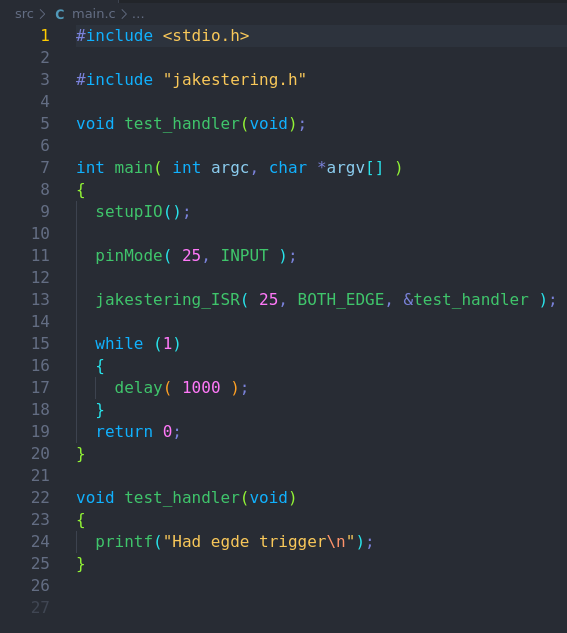
My main goal was to make the library as simple as possible, with functionality similar to Arduino code.
It works by mapping a block of memory starting from the address $20200000 which is the start of the GPIO registers.
gpioMap = mmap( NULL, BLOCK_SIZE, PROT_READ|PROT_WRITE, MAP_SHARED, memFd, GPIO_BASE );
Then, gpio is used as an index into this map.
gpio = ( volatile unsigned* )gpioMap;
This index is then used in a series of macros to affect the desired register.
#define INP_GPIO( g ) *( gpio + ( ( g ) / 10 ) ) &= ~( 7 << ( ( (g) % 10 ) * 3 ) )
#define OUT_GPIO( g ) *( gpio + ( ( g ) / 10 ) ) |=  ( 1 << ( ( (g) % 10 ) * 3 ) )
#define SET_GPIO_ALT( g, a ) *( gpio + ( ( ( g ) / 10 ) ) ) |= ( ( (a) <= 3 ? (a) + 4 : (a) == 4 ? 3 : 2) << ( ( (g) % 10 ) * 3 ) )

#define GPIO_SET *( gpio + 7 )
#define GPIO_CLR *( gpio + 10 )

#define GPIO_LEV( g ) ( *( gpio + 13 ) & ( 1 << g ) )

#define GPIO_EDS  *( gpio + 16 )
#define GPIO_REN  *( gpio + 19 )
#define GPIO_FEN  *( gpio + 22 )
#define GPIO_HEN  *( gpio + 25 )
#define GPIO_LEN  *( gpio + 28 )
#define GPIO_AREN *( gpio + 31 )
#define GPIO_AFEN *( gpio + 34 )

#define GPIO_PULL *( gpio + 37 )
#define GPIO_PULLCLK0 *( gpio + 38 )
Jakestering Pi has a simple set of useful functions to offer.
| Syntax | Description |
|---|---|
setupIO( void ) |
has to be called before any other function |
delay( int milliSeconds ) |
delay for n milli seconds |
delayMicro( int microSecond ) |
delay for n micro seconds |
pinMode( const int pin, const int mode ) |
sets x pin to INPUT/OUTPUT |
pudController( const int pin, const int PUD) |
set x pin to pull up/down/disable |
digitalWrite( const int pin, const int value ) |
set x pin to value |
digitalRead( const int pin ) |
returns the value of x pin |
digitalWriteByte( const int pin, const int pinStart, const int pinEnd ) |
writes a byte to a set of pins |
jakestering_ISR( const int pin, const int mode, void (*function)(void) |
x pin triggers an interrupt based on the mode |
ISR modes: Rising edge, Falling edge, Both edge, High detect, Low detect, Async Rising edge, Async Falling Edge
A simple binary counter test
The real work of the test program is done by the function outputCount. It loops through all 8-bits of an unsigned 8-bit number (count), shifting out each bit and testing whether or not it’s set, then writes that result to the respective pin (i + offset, i is what bit we are on, offset is what pin is going to be the LSB).
void outputCount( uint8_t count, int offset )
{
  for ( int i = 0; i < 8; i++ )
  {
    uint8_t bit = ( count >> ( i ) ) & 1;
    digitalWrite( i + offset, bit );
  }
}
EEPROM Programmer
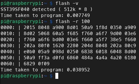
I developed software to program the SST39SF040 flash ROM using my library, JakesteringPi. It’s more than just a simple ROM programmer; It allows me to read to contents of the ROM, retrieve the device ID, write a raw binary file, erase the ROM, compare its contents against a raw binary file. While it should work for the entire family of SST39SF flash ROMs, I’ve only tested it with the SST39SF040. Expanding the code to support any 5v EEPROM would be trivial.
| Syntax | Description |
|---|---|
-h |
Display help |
-w file |
Write a binary file to flash device |
-r amount |
Read n bytes |
-v |
Check the flash’s device ID |
-c file |
Verify the contents of ROM are the same as file |
-e |
erase the whole ROM |
One of the challenges I faced when developing this programmer was. In order to write a byte, or do anything for that matter, you have to send a software command sequence to the SST39SF040. The one for writing a byte looks like this: write $AA to address $5555, then $55 to address $2AAA, then $A0 to address $5555, now write a byte to any address. There are 6 software command sequences: Byte-Program, Sector-Erase, Chip- Erase, Software ID Entry, and 2 different Software ID Exits.
  writeFlash( 0x5555, 0xaa );
  writeFlash( 0x2aaa, 0x55 );
  writeFlash( 0x5555, 0xa0 );
  writeFlash( addr  , byte );
taken from void byteProgram( unsigned int addr, unsigned int byte )
Logic Analyzer
I initially developed this to help debug problems on my 65c02 Workbench computer, but it has become an invaluable tool. It also utilizes my library, JakesteringPi. The software continuously monitors the GPIO lines of a Raspberry Pi Zero waiting for a interrupt. When triggered, it outputs the state of all the GPIO pins.
A typical setup for debugging the address, and data lines, clock, read/write
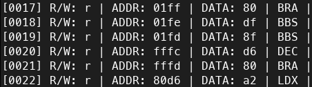
Logic Analyzer showing the 65c02 reset sequence
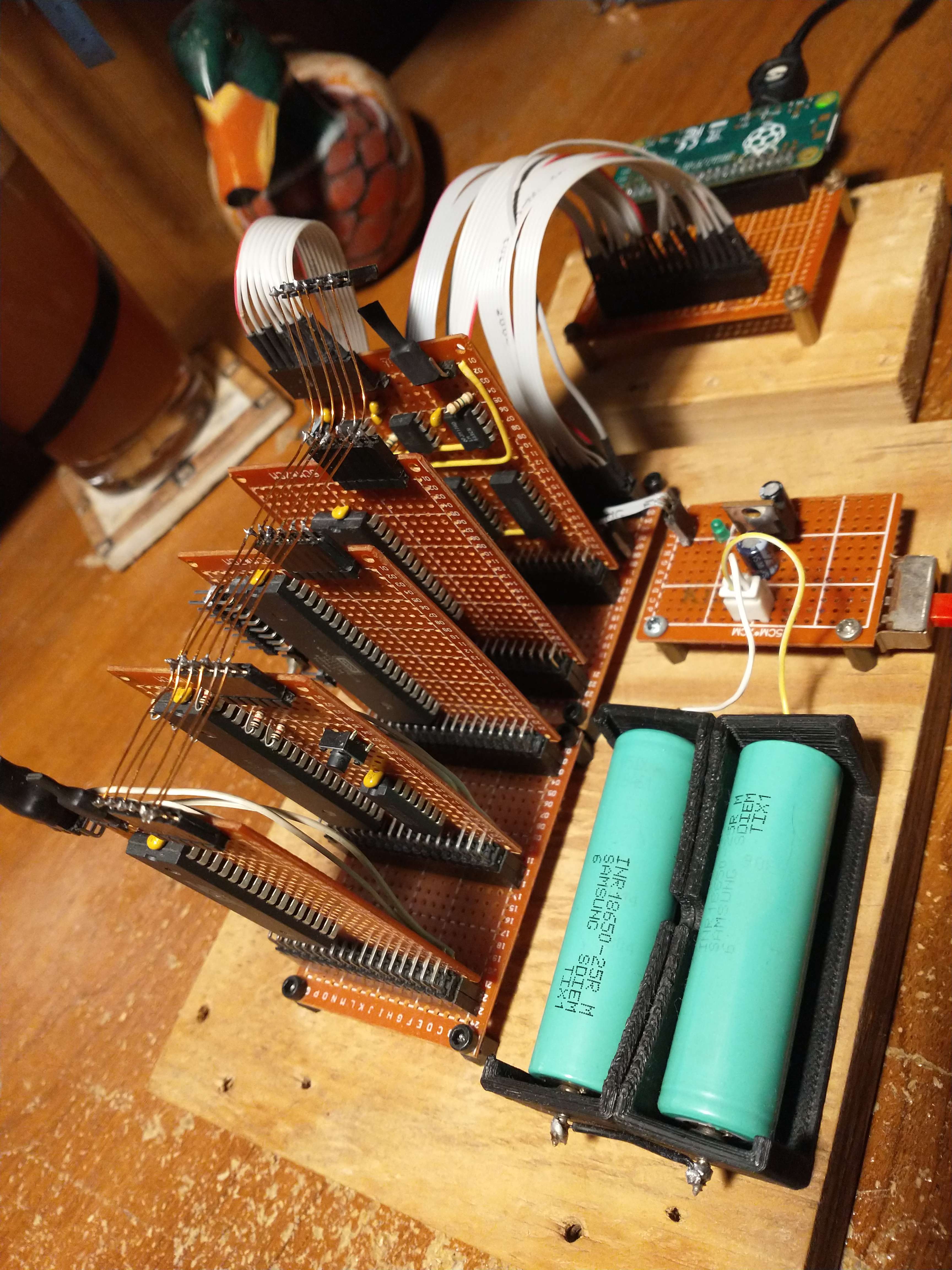
65c02 Workbench Computer
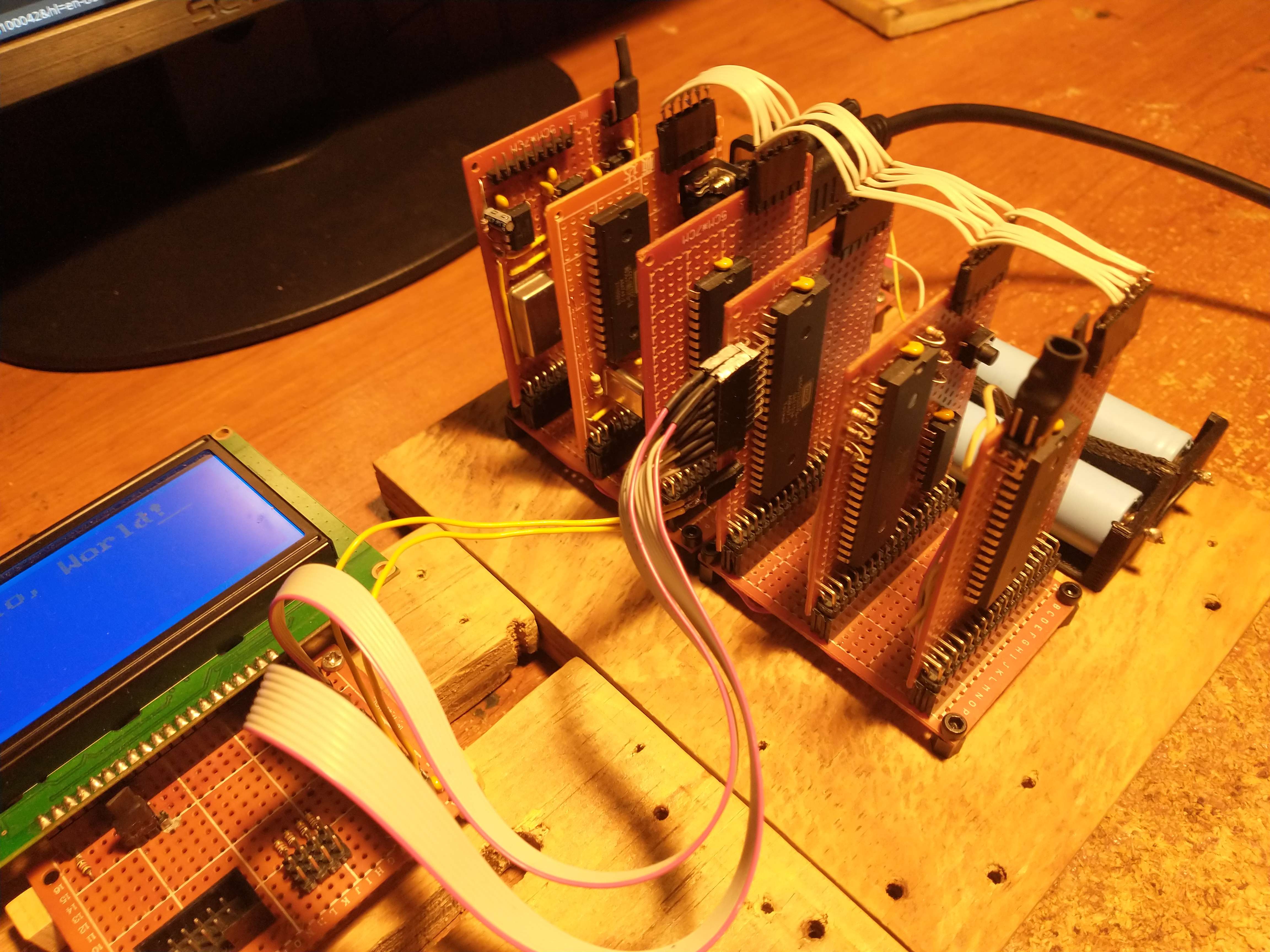
The main goal of this project is to meet my needs for programming EEPROMs, controlling external peripherals via SPI, I2C, and UART, controlling servos using PWM. Driving other miscellaneous logic devices.
The CPU is a WDC 65c02 running at 1 MHz. It includes an AS6C62256 32k x 8-bit static RAM, though the system uses only 16k for the main RAM. There is one 65c22 Versatile Interface Adapters (VIA), which features two 8-bit ports for general-purpose input/output. The 65c22 also enables the system to have timer-driven interrupts, based on its own internal timers. The computer has a 512k x 8-bit SST39SF040 flash ROM, with only 32k in use. This holds all the code for the BIOS, memory monitor, mini assembler/disassembler, and routines for interfacing with a 128x64 LCD. For communication, the system uses a 65c51 Asynchronous Communications Interface Adapter (ACIA), providing serial communication over RS232 with help from a MAX232 line driver.
One of the main factors considered during the initial development of the computer was cost. I wanted this machine to be as cheap as possible while using quality ICs. The entire build only cost me $82. Another key factor was to use components that I already had on hand, or could scavenge from e-waste. For instance, most of the wiring is from an old IDE cable. When that ran out, I switched to using enamel copper wire from shaded pole induction motor. The power supply uses a LM7805 from an old typewriter (interestingly, this typewriter had an M50747, which is a microcomputer on a chip with a CPU derived from the 6502).
Memory Map
| RAM | $0000 - $4000 |
| ACIA | $5000 - $5004 |
| VIA | $6000 - $600F |
| ROM | $8000 - $FFFF |
Software for the Workbench Computer
One of the first programs I developed for the system was a memory monitor. I took inspiration from WozMon and the monitor on the Apple II line of computers. I’d like to think my monitor is somewhat more sophisticated than WozMon. It allows for setting the current address to read from, starting execution at current address, writing n bytes to memory, reading n bytes back from memory, block-examining memory, showing the current address, examining and storing addresses (used internally), displaying the contents of the registers, and filling a range of memory with a value.
Memory Monitor Commands
| Description | Syntax |
|---|---|
| Change Address | a $xxxx |
| Write n bytes | w $xx $xx... |
| Read n bytes | r $xxxx |
| Execute | x |
| Block examine | b $xxxx $xxxx |
| Show Address | o |
| Show Registers | R |
| Fill range with value | f $xxxx $xxxx $xx |
| Open mini assembler | m |
| Open disassembler | l |
Writing programs with the memory monitor in machine language quickly became tedious, so I developed a mini assembler. It’s started from the memory monitor at the current address, allowing you to immediately begin writing assemble code.
;Here's a simple program to print out all the ASCII characters.

$0400: lda #$20
$0402: jsr $804d  ;This is the location of the CHAR_OUT routine
$0405: tax
$0406: inx
$0407: txa
$0408: jmp $0402
To help facilitate writing programs with the mini assembler I wrote a disassembler. It’s started from the memory monitor as well. Once started it converts the opcode at the current address into assembly language. side note: when the computer is first power on it does a RAM test and this leaves all of RAM as $00 The disassembler takes advantage of this when it encounters 4 $00 in a row it stops disassembling.
Future Software
- Memory allocator
- Forth system